

Tsunami
Product Catalog
Superior Filtration Products. Pure & Simple.
FILTERS | DRYERS | DRAINS | ACCESSORIES
.png "SuburbanManufacturing_Tsunami_PURE5_NoStand (full)")
%20updated.png "21999-0257 (2022) updated")
20 series
Prefer a downloadable version?
Download the complete Tsunami Product Catalog to save, share, or reference offline.

COMBINING QUALITY AND CUTTING-EDGE TECHNOLOGY

OPTIMIZED CONTENT
Our website works on a responsive template and is easily accessible on any hand-held device.
- Find in-depth information on the products you need.
- Get up-to-date information on new product releases and upcoming events.
- Download user manuals and instruction guides.
- Find up-to-date digital catalogs and product literature.
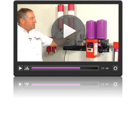
ONLINE VIDEOS
Tsunami Compressed Air Solutions™ offers over fifty online videos.
- Sales training and demonstration videos.
- View step-by-step installation instructions.
- General knowledge as well as tips and tricks on compressed air best practices.
Visit our YouTube channel or video library at:tsunami.us.com

For over 35 years, Tsunami Compressed Air Solutions™, has set the industry standard for quality compressed air filtration and drying solutions. While we strive to bring cutting-edge technology to the world of pneumatics, we continue to focus on the core principles that built the foundation of our successful business: quality, value, and world-class customer service.
At Suburban Manufacturing Group, our mission is to build value for our customers by producing quality, innovative, application-based products. Suburban is an engineering driven organization that partners with customers to design and develop unique and specific fluid power products.
Today, we distribute thousands of fluid power solutions worldwide right from our U.S. manufacturing facility located in Monticello, Minnesota.
Suburban Manufacturing Group is an ISO 9001-2015 Certified Manufacturer

THE #1 RULE OF
COMPRESSED AIR
For Every 20°F that Compressed Air is Cooled, the Air Loses 50% of its ability to Hold Moisture in Vapor Form (Humidity) and is Dropped Out as a Liquid.
UNDERSTANDING AIR DRYING AND AIR FILTRATION… THERE IS A DIFFERENCE!
AIR DRYING | The Removal of Water Vapor (Humidity) from Compressed Air
Typically, this is accomplished in one of four ways:
- Desiccant (molecular sieve, activated alumina, silica gel)
- Membrane
- Refrigeration
- Deliquescent
WHEN TO USE COMPRESSED AIR DRYERS
Air dryers should be used when you want to remove or reduce the humidity levels in your compressed air system to meet or exceed the air quality requirements for the compressed air demands of your tools, equipment, or applications.
AIR FILTRATION | The Removal of Particulates, Water, Oil Droplets, and Aerosols
This is most effective when done in stages:
- Water separator - removes bulk water, oil, and large particulates (down to 10 micron)
- Coalescing filter - removes oil, aerosols and fine particulates (down to .01 micron)
- Activated carbon filter - removes oil vapors; eliminates odors and taste (down to .003ppm)
WHERE TO PLACE COMPRESSED AIR FILTRATION
- The further away from the compressor, the more effective your filtration will work
- On or near the equipment, directly connected to air supply connection (IMPORTANT)
- In front of all air dryers as pre-filters
- Water separators should be placed at all air tool drops with regulators
IMPORTANT THINGS TO KNOW
- Proper control of air pressure throughout your facility can help save 10-15% of your compressed air energy costs.
- Repairing an audible air leak can save you $50 or more per year in energy used to drive your compressor.
- When sizing a compressor for manufacturing, it is important to calculate total machine air consumption as well as total air consumed by machine operators and other personnel.
- Proper control of air volume (CFM) will make all your air drying and filtration technology perform at their rated capacity. Most pieces of equipment have a manufacturer’s specification of volume consumption along with the recommended operating pressure.
- Improper use of volume can cause an “over-flowing” of the rated capacity of your dryer or filtration which causes a carry over of moisture and contaminants.
- Many OSHA approved blow off guns can consume up to 35 CFM, the equivalent of a 10 Hp compressor.
- Many color changing indicators used with desiccant systems do not begin to change color before 20% rH.
KEY QUESTIONS FOR APPLICATION SOLUTIONS
ABOUT THE APPLICATION
- How much air does the application/equipment need, in CFM?
- What pressure does the application require?
- How dry does the air have to be?
- Typically going to be specified as dew point or relative humidity
- How clean does the air have to be?
- Are we just worried about water, dirt, dust, and other particulates?
- Do we have to remove any oil aerosols from the air?
.png?width=300&height=238&name=SuburbanManufacturing_Tsunami_PURE5_NoStand%20(full).png)
ABOUT THE SUPPLY SIDE
- What types, and how many, compressors are in the facility?
- What is the horsepower rating of the compressor(s)?
- Do we know the output flow of the compressor?
- What is the output pressure of the compressor?
- What is the system pressure?
- What drying technology is used?
- Is the dryer installed before or after the receiver tank?
- Are there pre-filters used before the dryer?
- Are there filters after the dryer?
- Where, and how many, receiver tanks are installed?
- Is the system a looped system, “tree” layout, or a “dead stick” system?
%20updated.png?width=300&height=200&name=21999-0257%20(2022)%20updated.png)
THE TSUNAMI GUIDE TO ISO 8573-1:2010 STANDARDS
| Class | 0.1 pm < d < 0.5pm | 0.5 pm < d < 1.0pm | 1.0 pm < d < 5.0pm | Pressure Dew Point | Oil Content |
|---|---|---|---|---|---|
0 |
In accordance with the unit operator's or suppliers specifications, stricter requirements than class 1 |
In accordance with the unit operator's or suppliers specifications, stricter requirements than class 1 |
In accordance with the unit operator's or suppliers specifications, stricter requirements than class 1 |
In accordance with the unit operator's or suppliers specifications, stricter requirements than class 1 |
In accordance with the unit operator's or suppliers specifications, stricter requirements than class 1 |
1 |
≤ 20,000 |
≤ 400 |
≤ 10 |
≤ -94 |
≤ 0.01 |
2 |
≤ 400,000 |
≤ 6,000 |
≤ 100 |
≤ -40 |
≤ 0.1 |
3 |
- |
≤ 90,000 |
≤ 1,000 |
≤ -4 |
≤ 1 |
4 |
- |
- |
≤ 10,000 |
≤ 37 |
≤ 5 |
5 |
- |
- |
≤ 100,000 |
≤ 45 |
≤ 5 |
6 |
- |
- |
- |
≤ 50 |
- |
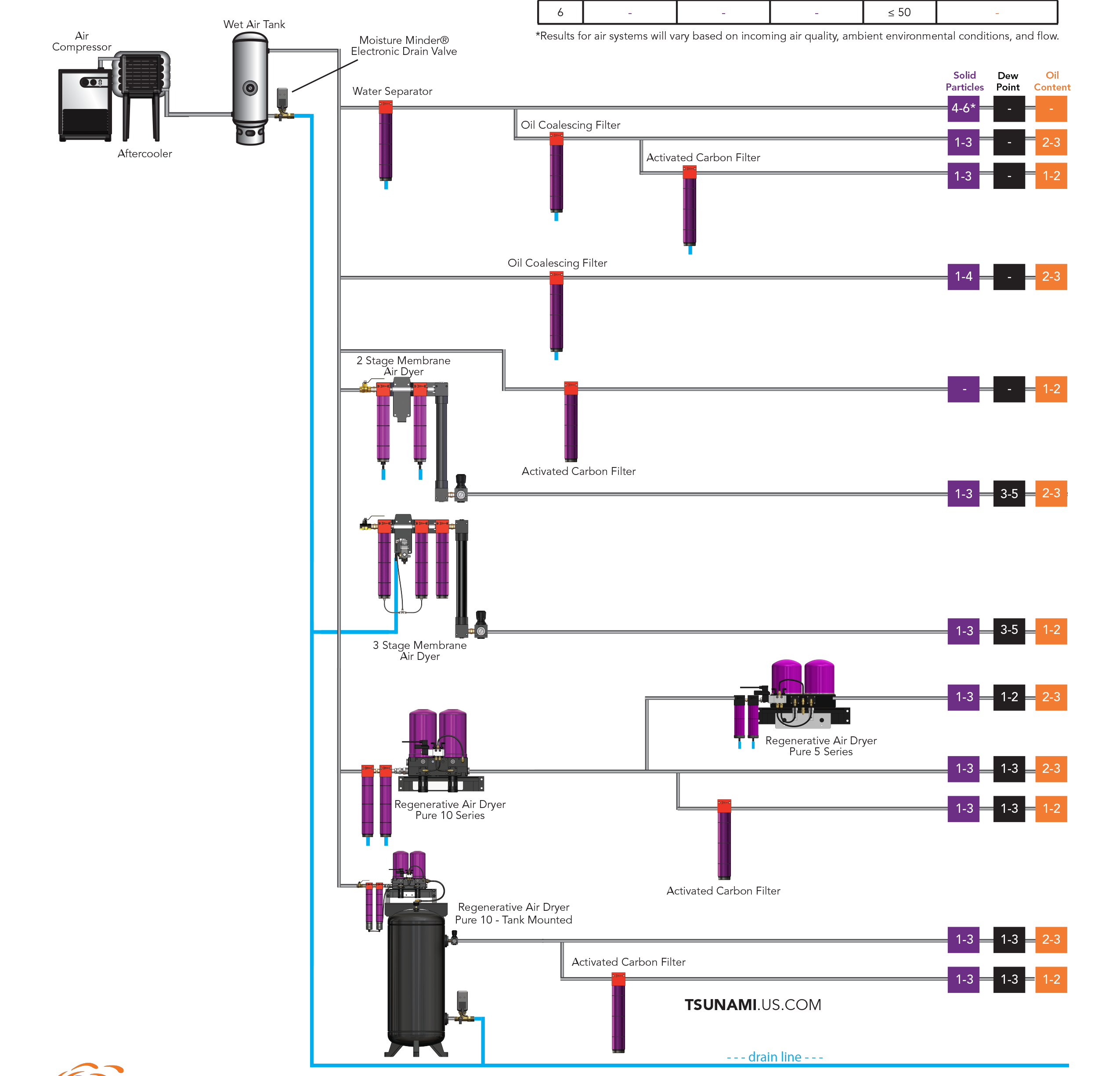
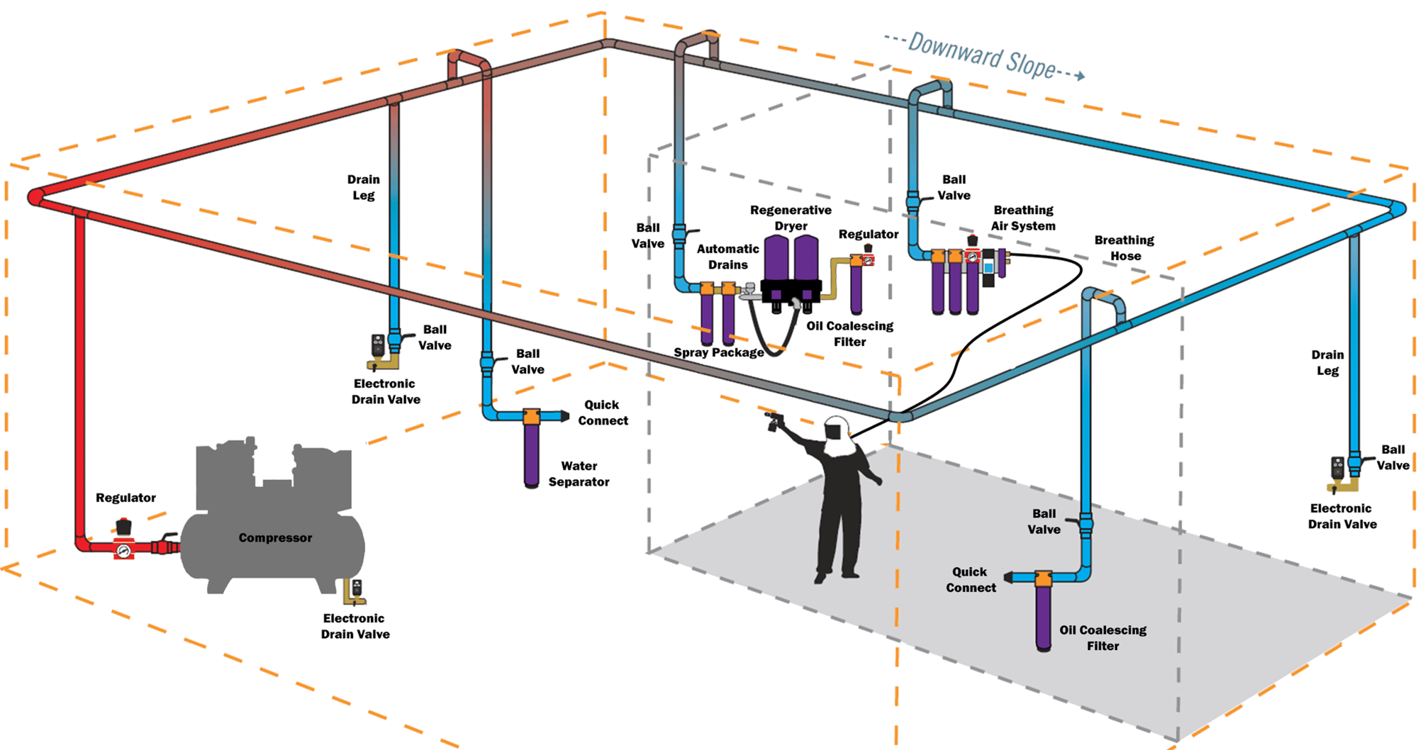
PROPER SHOP AIR SET UP
The further away from the air compressor, the more effective your air filtration will be. Compressed air filters should sit as close to the equipment as possible to catch condensed liquid in the piping.
For all compressed air systems, using some form of drying technology near the compressor is essential to an effectively designed air system. An air dryer is the final touch to prevent water from entering your equipment or application.
For applications requiring even dryer air, the ideal placement would be right before the point-of-use. This allows the compressed air to drop in temperature so the water vapor can be converted to liquid moisture and captured by the air filters; allowing for the dryer to remove any lingering humidity.
DRAINS:
There are three locations automatic drains are required to be present in order for an efficient, well-running system:
- Compressed air receiver tank: This allows for the draining of liquid that will condense in the tank and cause corrosion to the internal reservoir as well as take up valuable storage space for your compressed air volume.
- Anywhere there is a drip leg throughout the air piping: Placing an automatic drain on those drip legs removes collected moisture, thereby preventing it from being recaptured by the air stream. Catching and draining the liquid in the air pipes will ease the work of the air filters downstream downstream.
- On all air filters and air dryers: Automatic drains are recommended over manual drains in the event the operator forgets to drain the systems.
AIR DRYERS
Tsunami Regenerative Drying Systems use proprietary technology to provide extremely clean and dry air
- Low relative humidity - down to .01% RH
- Dew points down to -80°F
- Easy, low-cost maintenance - under $100/year average
- Includes Tsunami Water Separator and Oil Coalescing Filter with automatic drains
HOW IT WORKS
The Drying Process
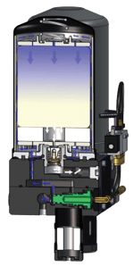
- Pre-filtered air enters the dryer and is channeled through the desiccant tower(s).
- Wet air passes through the tower(s) where molecular sieve desiccant draws water vapor in while under pressure.
- After flowing through the desiccant, the now dry air is sent downstream.
- After two minutes, the control timer sends out a pilot signal shifting the internal piston. When the piston shifts, air is redirected from the tower(s) to the opposite side.
The Regeneration Process
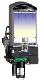
- A small amount of air from the dry outlet on the opposite tower(s) percolates up through the regeneration orifice and back through the desiccant filled tower(s).
- The desiccant is dried as the sweep air passes back through the media.
- With the use of this air, the tower(s) discharge water vapor through the mufflers.
- After two minutes, the control timer sends out a pilot signal shifting the internal piston. When the piston shifts, flow is reversed and this tower(s) begins drying the air.
WHICH IS BEST FOR YOUR APPLICATION?
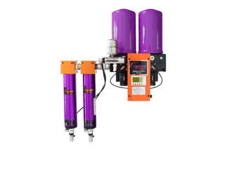
TSUNAMI REGENERATIVE DRYER
- Delivers ultra-low dew points (as low as –80°F)
- Designed for critical applications requiring extremely dry air
- Available in electric or fully pneumatic (C1D1) models
- Includes multi-stage filtration for maximum air quality
- More robust moisture removal for precision or sensitive processes
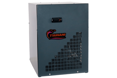
TSUNAMI REFRIGERATED DRYER
- Ideal for general-purpose compressed air systems
- Consistent dew points 38-50°F
- Lower upfront cost compared to regenerative systems
- Simple installation and low maintenance
- Best for non-critical application where ultra-low dew point is not required
ULTRA REGENERATIVE DRYERS
ULTRA SERIES REGENERATIVE DRYERS INCLUDE:
- 2-stage Pre-filtration*; Water Separator, Oil Coalescing Filter
- Regenerative Dryer
- Moisture Minder® Automatic Drains
- Programmable Logic Control (PLC)
- Heater pads availble for cold temp applications
ULTRA SERIES WALL-MOUNTED
Ultra series wall-mounted regenerative dryers are designed as complete packages. Systems can be configured in multiple variations allowing for pre-filtration to be installed on the left or right side of the unit. Dual inlet/outlet ports allow for bypass of the dryer where breathing air is required.
ULTRA SERIES TANK-MOUNTED
The optimal solution for any facility; simply connect shop air into the inlet fitting and out the regulator - it’s that simple. Tank-mounted dryers provide absolute ease of installation. A built-in bypass system allows the dryer to be shutoff for maintenance or service without stopping production.
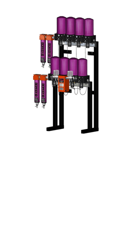
ULTRA SERIES RAIL-MOUNTED
Tsunami rail mounted regenerative dryers are built to withstand the largest surges of contamination. Similar to other Tsunami drying systems, these dual-inlet units are built as complete packages.
In addition to our complete line of standard products, Tsunami has engineered customizable dryers to meet air cleanliness requirements for a variety of industries and applications. Call 1.800.782.5752 or visit tsunami.us.com to learn more.
Dryer flow rates based on 100°F at 175 PSI with an outlet pressure of 100 PSI.* Lower inlet pressure and higher temperatures affect the performance and quality of the downstream air. *minimum recommended inlet pressure 80 PSI
Max pressure 175 PSI, max temperature 150°F 5/32 hex key required for piston bolts
.png?width=355&height=250&name=Tsunami%20Ultra%20Series%20Dryer%2021999-0710_new%20colors%20(1).png)
WALL-MOUNTED DRYERS
| ITEM # | MAX CFM | SIZE | TOWERS | DRAIN | PORT SIZE | WEIGHT | DIMENSIONS (HWD) |
|---|---|---|---|---|---|---|---|
21999-0710 |
40 |
10HP |
2 |
Pneumatic |
1"NPT |
73 lbs |
30" x 30" x 12" |
21999-0715 |
60 |
15HP |
3 |
Pneumatic |
1"NPT |
93 lbs |
30" x 36" x 12" |
21999-0720 |
80 |
20HP |
4 |
Pneumatic |
1"NPT |
118 lbs |
30" x 36" x 12" |
21999-0730 |
120 |
30HP |
4 |
Pneumatic |
1"NPT |
118 lbs |
30" x 36" x 12" |
TANK-MOUNTED DRYERS
| ITEM # | MAX CFM | SIZE | TOWERS | DRAIN | PORT SIZE | WEIGHT | DIMENSIONS (HWD) |
|---|---|---|---|---|---|---|---|
21999-0810 |
40 |
10HP |
2 |
Pneumatic |
1"NPT |
335 lbs |
69" x 51" x 27" |
21999-0815 |
60 |
15HP |
3 |
Pneumatic |
1"NPT |
358 lbs |
69" x 51" x 27" |
21999-0820 |
80 |
20HP |
4 |
Pneumatic |
1"NPT |
381 lbs |
69" x 51" x 27" |
21999-0830 |
120 |
30HP |
4 |
Pneumatic |
1"NPT |
381 lbs |
69" x 51" x 27" |
RAIL-MOUNTED DRYERS
| ITEM # | MAX CFM | SIZE | TOWERS | DRAIN | PORT SIZE | WEIGHT | DIMENSIONS (HWD) |
|---|---|---|---|---|---|---|---|
21999-0740 |
160 |
40HP |
8 |
Pneumatic |
1"NPT |
267 lbs |
66" x 36" x 21" |
21999-0750 |
200 |
50HP |
8 |
Pneumatic |
1"NPT |
267 lbs |
66" x 36" x 21" |
21999-0755 |
300 |
75HP |
12 |
Pneumatic |
1"NPT |
428 lbs |
66" x 36" x 42" |
21999-0760 |
400 |
100HP |
16 |
Pneumatic |
1"NPT |
534 lbs |
66" x 36" x 42" |
125 HP and 150 HP available on request. Call for details.
PURE REGENERATIVE DRYERS
SIMPLE. ECONOMICAL. EFFECTIVE.
- 2-stage Pre-filtration; Water Separator, Oil Coalescing Filter
- Regenerative Air Dryer
- Solenoid Valve Timer
- Automatic Drains
- Heater pads available for cold temp applications
1-Year Warranty on Tsunami Pure Drying Systems Utilizing Pneumatic Drains
PURE SERIES WALL-MOUNTED
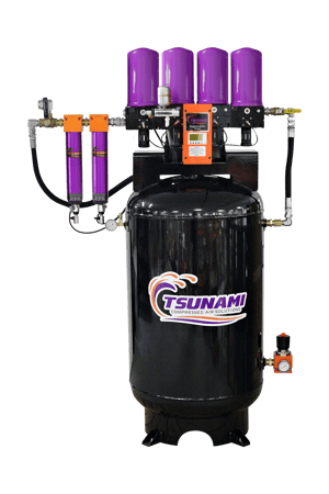
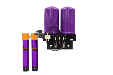
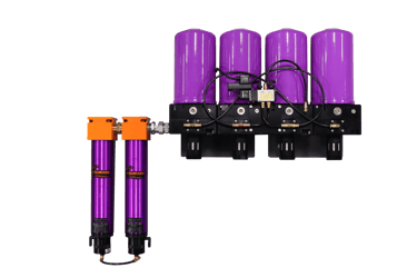
Pure systems utilize a simple timed control valve for cycling & Tsunami pre-filtration to assure removal of water, oil and particulates before entering the dryer.
Pure Series dryers are available with either float or Moisture Minder® pneumatic drains.
Dryer flow rates based on 100°F at 175 PSI with an outlet pressure of 100 PSI.*
Lower inlet pressure and higher temperatures affect the performance and quality of the downstream air
*minimum inlet pressure 80 PSI
.png?width=315&height=250&name=SuburbanManufacturing_Tsunami_PURE5_NoStand%20(full).png)
.png?width=250&height=250&name=23224_SMG_Tsunami_AirDryer_Pure10_21999-1010%20(new%20colors).png)
WALL-MOUNTED DRYERS
| ITEM # | MAX CFM | SIZE | TOWERS | POWER | DRAIN | PORT SIZE (NPT) | WEIGHT | DIMENSIONS (HWD) |
|---|---|---|---|---|---|---|---|---|
21999-1134 |
5 |
1 HP |
2 |
120v |
Float |
¼” inlet ½” outlet |
42 lbs |
15” x 22” x 8” |
21999-1134-MM |
5 |
1 HP |
2 |
120v |
Pneumatic |
¼” inlet ½” outlet |
42 lbs |
18” x 22” x 8” |
21999-1138 |
10 |
3 HP |
2 |
120v |
Float |
¼” inlet ½” outlet |
42 lbs |
15” x 22” x 8” |
21999-1138-MM |
10 |
3 HP |
2 |
120v |
Pneumatic |
¼” inlet ½” outlet |
42 lbs |
18” x 22” x 8” |
21999-1105 |
15 |
5 HP |
2 |
120v |
Float |
¼” inlet ½” outlet |
42 lbs |
15” x 22” x 8” |
21999-1105-MM |
15 |
5 HP |
2 |
120v |
Pneumatic |
¼” inlet ½” outlet |
42 lbs |
18” x 22” x 8” |
21999-1140 |
25 |
7.5 HP |
2 |
120v |
Float |
¼” inlet ½” outlet |
50 lbs |
26” x 25” x 8” |
21999-1140-MM |
25 |
7.5 HP |
2 |
120v |
Pneumatic |
¼” inlet ½” outlet |
50 lbs |
29” x 25” x 8” |
21999-1010 |
40 |
10 HP |
2 |
120v |
Float |
¼” inlet 1” outlet |
60 lbs |
26” x 25” x 8” |
21999-1010-220 |
40 |
10 HP |
2 |
220v |
Float |
¼” inlet 1” outlet |
60 lbs |
29” x 25” x 8” |
21999-1010-MM |
40 |
10 HP |
2 |
120v |
Pneumatic |
¼” inlet 1” outlet |
62 lbs |
26” x 25” x 8” |
21999-1010-MM-220 |
40 |
10 HP |
2 |
220v |
Pneumatic |
¼” inlet 1” outlet |
62 lbs |
26” x 25” x 8” |
21999-1010-MM-24 |
40 |
10 HP |
2 |
24v |
Pneumatic |
¼” inlet 1” outlet |
62 lbs |
29” x 25” x 8” |
21999-1020 |
80 |
20 HP |
4 |
120v |
Float |
1” NPT |
112 lbs |
27” x 36” x 9” |
21999-1020-MM |
80 |
20 HP |
4 |
120v |
Pneumatic |
1” NPT |
112 lbs |
30” x 36” x 9” |
21999-1030 |
120 |
30 HP |
6 |
120v |
Float |
1” NPT |
150 lbs |
27” x 48” x 9” |
21999-1030-MM |
120 |
30 HP |
6 |
120v |
Pneumatic |
1” NPT |
150 lbs |
30” x 48” x 9” |
PURE SERIES TANK DRYERS
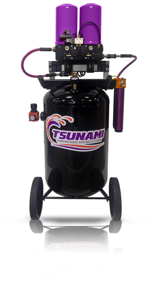
The Pure Series Tank-Mounted dryers come as a complete package with tank attachments to support air flow. The Pure-5T comes with a 1-gallon tank to maximize laminar air flow and the Pure-10T sits atop a 60-gallon storage tank for increased dry air storage.
TSUNAMI PORTABLE DRYERS
Tsunami’s Portable Dryers are designed to give you ultimate mobility. These user friendly designs provide Tsunami world class air quality in a portable package.
.png?width=500&height=750&name=21999-0955%20Pure%2010%20series%20tank%20dryer_new%20colors%20(full).png)

TANK DRYERS
| ITEM # | MAX CFM | SIZE | TOWERS | POWER | DRAIN | PORT SIZE (NPT) | WEIGHT | DIMENSIONS (HWD) |
|---|---|---|---|---|---|---|---|---|
21999-1105-T |
15 |
5 HP |
2 |
120v |
Pneumatic |
¼” inlet ¼” outlet |
50 lbs |
17” x 24” x 8” |
21999-1105-T-MM |
15 |
5 HP |
2 |
120v |
Pneumatic |
¼” inlet ¼” outlet |
51 lbs |
20” x 24” x 8” |
21999-0955 |
40 |
10 HP |
2 |
120v |
Pneumatic |
½” NPT |
190 lbs |
72” x 36” x 23” |
21999-0955-220 |
40 |
10 HP |
2 |
220v |
Pneumatic |
½” NPT |
190 lbs |
72” x 36” x 23” |
MOBILE/PORTABLE DRYERS
| ITEM # | MAX CFM | SIZE | TOWERS | POWER | DRAIN | PORT SIZE (NPT) | WEIGHT | DIMENSIONS (HWD) |
|---|---|---|---|---|---|---|---|---|
21999-1100 |
15 |
5 HP |
2 |
120v |
Float |
¼” inlet ¼” outlet |
51 lbs |
23” x 25” x 12” |
21999-1100-MM |
15 |
5 HP |
2 |
120v |
Pneumatic |
¼” inlet ¼” outlet |
51 lbs |
23” x 25” x 12” |
21999-0945 |
40 |
10 HP |
2 |
120v |
Float |
½” NPT |
150 lbs |
53” x 33” x 22” |
REFRIGERATED DRYERS
ECONOMICAL. EFFICIENT. RELIABLE.
The Tsunami Refrigerated Dryer is engineered to remove excess water vapor from compressed air lines. By lowering the dew point and reducing the humidity entering downstream equipment, the Refrigerated Dryer increases job efficiency, extends equipment life, and minimizes costly downtime. Designed for every-day long-term use, this costeffective technology improves application finishes while decreasing product waste and improving overall operations and :
- Low initial cost
- Consistent dew point (38-50°F)
- UL/CSA certified
- Patented heat exchanger
- Energy-efficient
- Integrated automatic moisture drain
- Simple, compact plug-and-play design
- Reliable & easy to maintain
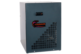
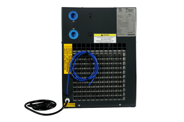
1-Year Warranty on Tsunami Refrigerated Dryers
- Prevents corrosion, water damage, and defects caused by moisture
- Reduces energy during low-demand periods; efficiency without compromising performance
- No manual draining needed
- Integrated automatic moisture drain
- For tight spaces & integration
- Reduces downtime
| ITEM # | DESCRIPTION | CFM | NPT | MAX PSI | MAX °F | WEIGHT | POWER |
|---|---|---|---|---|---|---|---|
RSD-015 |
15 CFM Refrigerated Series Dryer |
15 |
3/4” |
232 |
130 |
39 lbs |
115 VAC |
RSD-020 |
20 CFM Refrigerated Series Dryer |
20 |
3/4” |
232 |
130 |
39 lbs |
115 VAC |
RSD-035 |
35 CFM Refrigerated Series Dryer |
35 |
3/4” |
232 |
130 |
41 lbs |
115 VAC |
RSD-050 |
50 CFM Refrigerated Series Dryer |
50 |
3/4” |
232 |
130 |
45 lbs |
115 VAC |
RSD-075 |
75 CFM Refrigerated Series Dryer |
75 |
1” |
232 |
130 |
58 lbs |
115 VAC |
RSD-100 |
100 CFM Refrigerated Series Dryer |
100 |
1” |
232 |
130 |
75 lbs |
115 VAC |
RSD-125 |
125 CFM Refrigerated Series Dryer |
125 |
1” |
232 |
130 |
86 lbs |
115 VAC |
RSD-150 |
150 CFM Refrigerated Series Dryer |
150 |
1” |
232 |
130 |
88 lbs |
115 VAC |
RSD-175 |
175 CFM Refrigerated Series Dryer |
175 |
1 1/2” |
232 |
130 |
119 lbs |
115 VAC |
RSD-220 |
220 CFM Refrigerated Series Dryer |
220 |
1 1/2” |
232 |
130 |
157 lbs |
230 VAC |
RSD-300 |
300 CFM Refrigerated Series Dryer |
300 |
1 1/2” |
232 |
130 |
170 lbs |
230 VAC |
MEMBRANE DRYERS
SIMPLE AIR DRYING TECHNOLOGY
Tsunami Membrane Dryers provide an economical solution for supplying clean, dry air without the need for electricity. The molecular makeup of the hollow tubes allows water vapor to pass. The greater the pressure differential between the inlet and outlet pressures, the drier the air downstream.
- Low relative humidity - down to .01% RH
- Great dew point supression - up to 140°F swing
- Easy, low-cost maintenance - $160/year
- Includes Tsunami Water Separator and Oil Coalescing Filter pre-filtration with automatic drains
HOW IT WORKS
The Drying Process
- The molecular makeup of the hollow tubes allows certain gases to pass through the membrane quicker than the desired gas.
- As compressed air travels through the hollow tubes, water vapor passes through the membrane pores.
- The water vapor collects within the housing until it is removed.
- A fixed orifice at the bottom of the hollow tubes allows dry air to pass up the housing, around the hollow tubes, to sweep the water vapor out the sweep holes at the top of the housing.
MEMBRANE DRYER
Includes:- 2-Stage Pre-filtration
- Outlet Regulator
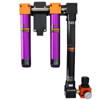
MacPressure 175 psi | Max Temperature: 100°F
| ITEM # | MAX CFM | PORT SIZE | WEIGHT | DIMENSIONS (HWD) |
|---|---|---|---|---|
21999-0889 |
15 |
¼” NPT |
16½ lbs |
22” x 12” x 3½” |
21999-0357 |
20 |
½” NPT |
16½ lbs |
23” x 20” x 4½” |
21999-0355 |
Membrane Core Replacement |
Membrane Core Replacement |
Membrane Core Replacement |
Membrane Core Replacement |
PRECISION MEMBRANE DRYER
Includes:- 3-Stage Pre-filtration
- Electronic Drain
- Outlet Regulator
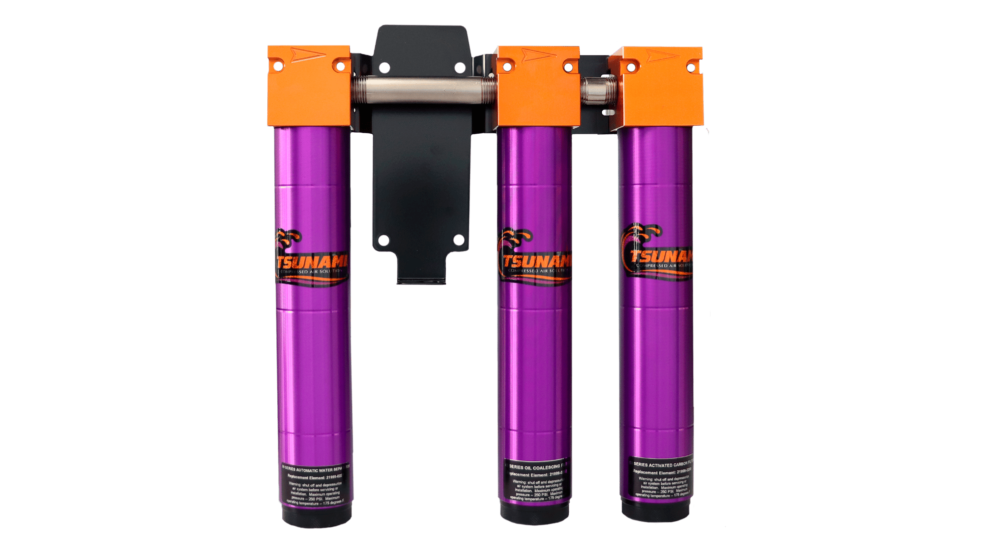
MacPressure 175 psi | Max Temperature: 100°F
| ITEM # | MAX CFM | PORT SIZE | WEIGHT | DIMENSIONS (HWD) |
|---|---|---|---|---|
21999-0957 |
15 |
¼” NPT |
12 lbs |
24½” x 18½” x 5½” |
21999-0524 |
20 |
½” NPT |
22 lbs |
23” x 23½” x 5½” |
21999-0355 |
Membrane Core Replacement |
Membrane Core Replacement |
Membrane Core Replacement |
Membrane Core Replacement |
CORE DESICCANT DRYER
“CORE” AIR DRYING TECHNOLOGY
The Tsunami CORE Series Desiccant Air Dryer provides world-class air dryness at an affordable price, designed solely for intermittent, lower pressure point-of-use applications.
- 2-stage Pre-filtration with Automatic Drains
- Desiccant Air Dryer - 20% longer media life
- Corrosion-resistant interior
- Super easy maintenance
- Removes liquids, oils, particulates and humidity, dew points down to
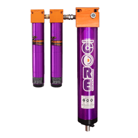
| ITEM # | DESCRIPTION | PORT SIZE (NPT) | DRAIN | MAX PSI | MAX °F | WEIGHT | DIMENSIONS (IN) |
|---|---|---|---|---|---|---|---|
21999-1225 |
Desiccant Air Dryer System with Pre-Filtration - 25 CFM |
½ INLET / OUTLET |
Float |
200 |
175 |
25 lbs |
22 x 13 x 7 |
21999-1235 |
Desiccant Air Dryer without Pre-Filtration - 25 CFM |
½ INLET / OUTLET |
Float |
200 |
175 |
14 lbs |
22 x 5 x 7 |
HIGH TEMPERATURE REGENERATIVE DRYERS
ALL-IN-ONE SYSTEM FOR MOBILE APPLICATIONS
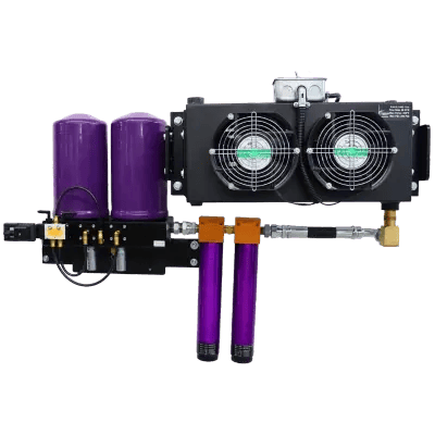
The Tsunami High Temperature Regenerative Drying System is a complete, ready-to-install package designed for mobile and small-flow applications. By combining a wall-mounted 50 CFM aftercooler with proven regenerative desiccant drying technology, it delivers consistently dry, high-quality air in high-temperature environments. This system maintains lower dew points and reliable performance, making it ideal for mobile cabins, trailers, and compact workshops. Its compact, allin-one design maximizes efficiency, frees floor space, and reduces setup time.
- All-in-one system: Aftercooler, Regenerative Dryer, and Pre-filtration Package (Water Separator & Oil Coalescing)
- Dew point as low as -40°F
- 300°F max inlet temp
- Removes up to 75% of condensation
- Wall-mountable
- Integrated automatic drain
- Compact design
1-Year Warranty on Tsunami High Temperature Regenerative Dryers
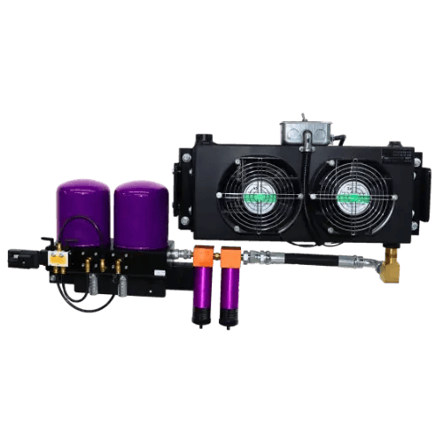
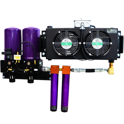
- Improves system performance
- Increases floor & operating space in tight spaces
- All-in-one system allows for a quick, one-time setup
- Improve application coatings
- Have efficient operations
| ITEM # | DESCRIPTION | CFM | PORT SIZE | MAX PSI | MAX °F | WEIGHT | DIMENSIONS (IN) | POWER |
|---|---|---|---|---|---|---|---|---|
21999-1255 |
High Temperature Pure 5 Regenerative Dryer |
15 |
3/4"INLET, 1/2" OUTLET |
175 |
300 |
83 lbs |
22 x 38 x 13 |
120 VAC |
21999-1257 |
High Temperature Pure 7 Regenerative Dryer |
25 |
3/4"INLET, 1/2" OUTLET |
175 |
300 |
88 lbs |
22 x 38 x 13 |
120 VAC |
21999-1260 |
High Temperature Pure 10 Regenerative Dryer |
40 |
3/4"INLET, 1" OUTLET |
175 |
300 |
92 lbs |
22 x 38 x 13 |
120 VAC |
C1D1 PNEUMATIC DRYER
FOR CLASS 1, DIVISON 1 HAZARDOUS LOCATIONS
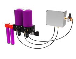
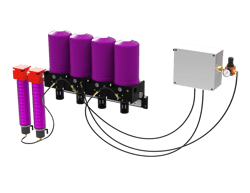
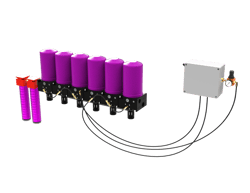
The Tsunami C1D1 Pneumatic Air Dryer is engineered for Class 1, Division 1 hazardous locations with the ability to provide safe and reliable compressed air drying without the use of electricity. Designed for environments where flammable gases or vapors are present, it eliminates ignition risks while delivering clean, dry air to protect tools, equipment, and processes. The C1D1 dryer is ideal for maintaining safety and performance in explosive or volatile conditions.
- No electricity required
- ATEX compliant components
- Explosion-proof components
- Low dew points to prevent freezing in air pipes
- Pneumatic-powered Controller
- Wall-brackets or Floor Mount Stand
- Regenerative Dryer
- Includes Tsunami Water Separator and Oil Coalescing Filter
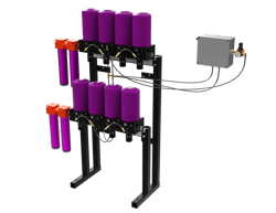
WITH FLOAT DRAINS
| ITEM # | DESCRIPTION | TOWER # | CFM | DRAIN | WATER SEPARATOR | OIL COALESCING | MOUNT |
|---|---|---|---|---|---|---|---|
21999-1310 |
40 CFM Class 1 Division 1 Hazardous Location Regenerative Drying System with Float Drains |
2 |
40 |
Float |
1 x 50 Series |
1 x 50 Series |
Wall |
21999-1320 |
80 CFM Class 1 Division 1 Hazardous Location Regenerative Drying System with Float Drains |
4 |
80 |
Float |
1 x 120 Series |
1 x 120 Series |
Wall |
21999-1330 |
120 CFM Class 1 Division 1 Hazardous Location Regenerative Drying System with Float Drains |
6 |
120 |
Float |
1 x 120 Series |
1 x 120 Series |
Wall |
21999-1340 |
160 CFM Class 1 Division 1 Hazardous Location Regenerative Drying System with Float Drains |
8 |
160 |
Float |
2 x 120 Series |
2 x 120 Series |
Rail |
21999-1350 |
200 CFM Class 1 Division 1 Hazardous Location Regenerative Drying System with Float Drains |
12 |
200 |
Float |
2 x 120 Series |
2 x 120 Series |
Rail |
21999-1355 |
300 CFM Class 1 Division 1 Hazardous Location Regenerative Drying System with Float Drains |
18 |
300 |
Float |
3 x 120 Series |
3 x 120 Series |
Rail |
21999-1360 |
400 CFM Class 1 Division 1 Hazardous Location Regenerative Drying System with Float Drains |
24 |
400 |
Float |
4 x 120 Series |
4 x 120 Series |
Rail |
WITH PNEUMATIC DRAINS
| ITEM # | DESCRIPTION | TOWER # | CFM | DRAIN | WATER SEPARATOR | OIL COALESCING | MOUNT |
|---|---|---|---|---|---|---|---|
21999-1310-MM |
40 CFM Class 1 Division 1 Hazardous Location Regenerative Drying System with Pneumatic Drains |
2 |
40 |
Pneumatic |
1 x 50 Series |
1 x 50 Series |
Wall |
21999-1320-MM |
80 CFM Class 1 Division 1 Hazardous Location Regenerative Drying System with Pneumatic Drains |
4 |
80 |
Pneumatic |
1 x 120 Series |
1 x 120 Series |
Wall |
21999-1330-MM |
120 CFM Class 1 Division 1 Hazardous Location Regenerative Drying System with Pneumatic Drains |
6 |
120 |
Pneumatic |
1 x 120 Series |
1 x 120 Series |
Wall |
21999-1340-MM |
160 CFM Class 1 Division 1 Hazardous Location Regenerative Drying System with Pneumatic Drains |
8 |
160 |
Pneumatic |
2 x 120 Series |
2 x 120 Series |
Rail |
21999-1350-MM |
200 CFM Class 1 Division 1 Hazardous Location Regenerative Drying System with Pneumatic Drains |
12 |
200 |
Pneumatic |
2 x 120 Series |
2 x 120 Series |
Rail |
21999-1355-MM |
300 CFM Class 1 Division 1 Hazardous Location Regenerative Drying System with Pneumatic Drains |
18 |
300 |
Pneumatic |
3 x 120 Series |
3 x 120 Series |
Rail |
21999-1360-MM |
400 CFM Class 1 Division 1 Hazardous Location Regenerative Drying System with Pneumatic Drains |
24 |
400 |
Pneumatic |
4 x 120 Series |
4 x 120 Series |
Rail |
AFTERCOOLER
FOR LOWERING HIGH HEAT FROM AIR COMPRESSORS
The Tsunami Aftercooler delivers exceptional air cooling, critical for applications sensitive to moisture contamination. By significantly reducing the moisture load entering downstream dryers, the Aftercooler optimizes dryer performance, extends equipment life, and minimizes costly downtime. Engineered for challenging environments with high ambient temperatures, the Tsunami Aftercooler ensures reliable and efficient compressed air supply for demanding applications, maximizing system uptime and productivity.
- Cools & condenses water vapor into liquid moisture for easy removal
- Great dew point supression - up to 140°F swing
- Bar & plate heat exchanger
- Pre-cools hot compressed air before entering dryers
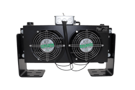
WALL-MOUNTED AFTERCOOLER
The Tsunami Aftercooler’s wall-mount design eliminates the need for extended piping runs and floor spaceconsuming stands, streamlining installation and maximizing workspace. With 6 wall-mounting configurations, you gain complete conytol over installation, enabling efficient water removal and minimizing the risk of corrosion, freezing, and contamination
- 6 wall-mounting configurations allow for optimal performance & spacial requirements
- Choose approach temperature based on wall-mounting configuration
- Increase floor & operating space with wall-mount
- For mobile applications, spray foam, mobile paint equipment, and mobile tire rigs
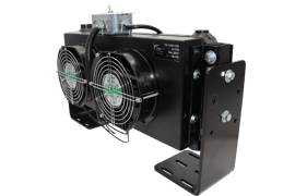
| ITEM # | DESCRIPTION | PORT SIZE (NPT) | MAX PSI | MAX °F | AMPS | POWER |
|---|---|---|---|---|---|---|
21999-1250 |
Aftercooler |
3/4" |
290 |
300 |
0.4 |
120 VAC |
Required: Install a water separator to remove all condensed moisture downstream.
There are six installation configurations for the Tsunami Aftercooler. Choose the best option that fits the space available to you and specific application goals.
GOOD
Performance: 15 - 20°F
4.3" AIR COOLING CLEARANCE
Horizontal, Parallel to Wall
%2016in.png?width=293&height=226&name=Horizontal%20parallel%20and%20close%20to%20the%20wall%20bracket%20orientation%20(good)%2016in.png)
Dimensions:
22.5" x 11.75" x 10.25"
Vertical, Parallel to Wall
.png?width=293&height=226&name=Vertical%20parallel%20and%20close%20to%20the%20wall%20(good).png)
Dimensions:
11.75" x 28" x 10.25"
BETTER
Performance: 10 - 15°F
6.6" AIR COOLING CLEARANCE
Horizontal, Parallel to Wall
%2016in.png?width=293&height=226&name=Horizontal%20parallel%20and%20farther%20from%20the%20wall%20bracket%20orientation%20(better)%2016in.png)
Dimensions:
22.5" x 11.75" x 12.5"
Vertical, Parallel to Wall
.png?width=293&height=226&name=Vertical%20parallel%20and%20farther%20from%20the%20wall%20(better).png)
Dimensions:
11.75" x 28" x 12.5"
Best
Performance: 5 - 10°F
UNOBSTRUCTED AIR COOLING CLEARANCE
Horizontal, Perpendicular to Wall
%2016in.png?width=293&height=226&name=Horizontal%20perpendicular%20from%20the%20wall%20(best)%2016in.png)
Dimensions:
22.5" x 7.25" x 14.25"
Vertical, Perpendicular to Wall
.png?width=293&height=226&name=Vertical%20perpendicular%20from%20the%20wall%20(best).png)
Dimensions:
7.25" x 28" x 14.25"
AIR FILTRATION
FOR THE SURGES ORDINARY FILTERS CAN’T HANDLE
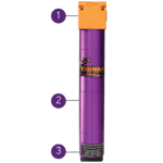
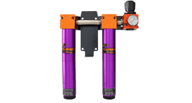
Tsunami filters are machined from the highest quality materials and are anodized inside and out to ensure ultimate durability against corrosion and trapped contaminates. Our cutting-edge technology is rigorously tested to outperform your expectations regardless of the industry or application.
- Filter heads machined from 6061 Aircraft Aluminum
- Oversized tube length allows both gravity and velocity to assist in the removal of water and air contaminates
- Removable bottom cap provides ease of service and machined drain port provides various drain capabilities
%20updated.png?width=225&height=150&name=21999-0257%20(2022)%20updated.png)
-R Filter packages can be ordered in reverse flow, right to left, and have a “-R” at the end of the part number
Filtration service parts can be found on pages 18-19 or by searching the unit part number online at tsunami.us.com
WATER SEPARATORS
The Tsunami Water Separator removes water, up to one quart per minute, and filters particulate down to 10 micron.
HOW IT WORKS
- Air enters the filter & travels down a small diameter tube causing an increase in velocity.
- The air reaches the bottom of the inner tube then is redirected 180° up the outer tube allowing gravity and a slower velocity to capture bulk liquids.
- Velocity increases again as air is forced through small orifice baffles before entering the stainless steel mesh element.
- Centrifugal force is used to capture any remaining liquids before exiting the filter.
- Liquids are automatically ejected through the drain.
Max Pressure: 250 psi (20-120 CFM) 200 psi (300-800 CFM)
Max Temperature: 175°F
| ITEM # | MAX CFM | DRAIN TYPE | PORT SIZE | WEIGHT | DIMENSIONS(HWD) |
|---|---|---|---|---|---|
21999-0390 |
20 |
Float |
¼” NPT |
1½ lbs |
8½” x 2” x 2” |
21999-0390-ED |
20 |
Electronic |
¼” NPT |
2½ lbs |
11½” x 2” x 2” |
21999-0390-MM |
20 |
Pneumatic |
2 NPT |
2 lbs |
10½” x 2” x 2” |
21999-0131 |
50 |
Float |
½ ” NPT |
3½ lbs |
14½” x 2½” x 2½” |
21999-0131-ED |
50 |
electronic |
½ ” NPT |
6 lbs |
17½” x 5½” x 4” |
21999-0131-MM |
50 |
Pneumatic |
½” NPT |
6 lbs |
17” x 2½” x 2½” |
21999-1034 |
120 |
Float |
¾” NPT |
9 lbs |
16” x 3½” x 3½” |
21999-1034-ED |
120 |
Electronic |
¾” NPT |
9½ lbs |
18” x 6” x 4½” |
21999-1034-MM |
120 |
Pneumatic |
¾” NPT |
9 lbs |
18” x 3½” x 3½” |
21999-0082 |
120 |
Float |
1” NPT |
9 lbs |
16” x 3½” x 3½” |
21999-0082-ED |
120 |
Electronic |
1” NPT |
9½ lbs |
18” x 6” x 4½” |
21999-0082-MM |
120 |
Pneumatic |
1” NPT |
9 lbs |
18” x 3½” x 3½” |
21999-1150 |
225 |
Float |
1½” NPT |
12 lbs |
22” x 4½” x 6½” |
21999-1150-ED |
225 |
Electronic |
1½” NPT |
13 lbs |
25” x 4½” x 6½” |
21999-1150-MM |
225 |
Pneumatic |
1½” NPT |
14 lbs |
26” x 4½” x 10” |
21999-1096 |
300 |
Float |
1½” NPT |
12 lbs |
28” x 4½” x 6½” |
21999-1096-ED |
300 |
Electronic |
1½” NPT |
13 lbs |
31” x 4½” x 6½” |
21999-1096-MM |
300 |
Pneumatic |
1½” NPT |
14 lbs |
32” x 4½” x 10” |
21999-1160 |
450 |
Float |
2” NPT |
19 1/2 |
26" X 5½" X 5½" |
21999-1160-ED |
450 |
Electronic |
2” NPT |
20 1/2 |
28" X 5½" X 5½" |
21999-1160-MM |
450 |
Pneumatic |
2” NPT |
21 1/2 |
29" X 5½" X 5½" |
21999-1120 |
600 |
Float |
2” NPT |
20 lbs |
31” x 5½” x 5½” |
21999-1120-ED |
600 |
Electronic |
2” NPT |
21 lbs |
34” x 5½” x 5½” |
21999-1120-MM |
600 |
Pneumatic |
2” NPT |
22 lbs |
35” x 5½” x 5½” |
21999-0960 |
800 |
Float |
3” NPT |
45 lbs |
35½” x 6” x 6” |
21999-0960-ED |
800 |
Electronic |
3” NPT |
46 lbs |
35½” x 6” x 10” |
21999-0960-MM |
800 |
Pneumatic |
3” NPT |
46 lbs |
35½” x 6” x 8½” |
OIL COALESCING FILTERS
The Oil Coalescing Filter removes bulk oils, aerosols, and particulates down to .01 micron/ppm aerosols.
HOW IT WORKS
- Air enters the filter and passes through the element from the center to the outside.
- As the air travels through the fibrous layers, oil aerosols are captured and coalesce.
- The non-wicking outer drain layer separates the bulk liquids from the air flow.
- Gravity slows the bulk liquids to drip into the drain sump off the filter where they are automatically removed.
Replace element every six months
Max Pressure: 250 psi (20-120 CFM) 200 psi (300-800 CFM)
Max Temperature: 175°F
| ITEM # | MAX CFM | DRAIN TYPE | PORT SIZE | WEIGHT | DIMENSIONS(HWD) |
|---|---|---|---|---|---|
21999-0390-Z-FD |
20 |
Float |
¼” NPT |
1½ lbs |
8½” x 2” x 2” |
21999-0390-Z-ED |
20 |
electronic |
¼” NPT |
2½ lbs |
11½” x 2” x 2” |
21999-0390-Z-MM |
20 |
Pneumatic |
¼” NPT |
2 lbs |
10½” x 2” x 2” |
21999-0131-Z-FD |
50 |
Float |
½” NPT |
3½ lbs |
14½” x 2½” x 2½” |
21999-0131-Z-ED |
50 |
Electronic |
½” NPT |
4½ lbs |
17½” x 5½” x 4” |
21999-0131-Z-MM |
50 |
Pneumatic |
½” NPT |
4 lbs |
17” x 2½” x 2½” |
21999-1034-Z-FD |
120 |
Float |
¾” NPT |
5 lbs |
16” x 3½” x 3½” |
21999-1034-Z-eD |
120 |
Electronic |
¾” NPT |
6 lbs |
18” x 6” x 4½” |
21999-1034-Z-MM |
120 |
Pneumatic |
¾” NPT |
5½ lbs |
18” x 3½” x 3½” |
21999-0082-Z-FD |
120 |
Float |
1” NPT |
5 lbs |
16” x 3½” x 3½” |
21999-0082-Z-ED |
120 |
Electronic |
1” NPT |
6 lbs |
18” x 6” x 4½” |
21999-0082-Z-MM |
120 |
Pneumatic |
1” NPT |
5½ lbs |
18” x 3½” x 3½” |
21999-1150-Z-FD |
225 |
Float |
1½” NPT |
11 lbs |
22” x 4½” x 10” |
21999-1150-Z-ED |
225 |
Electronic |
1½” NPT |
12 lbs |
25” x 4½” x 10” |
21999-1150-Z-FDMM |
225 |
Pneumatic |
1½” NPT |
12 lbs |
26” x 4½” x 10” |
21999-1096-Z-FD |
300 |
Float |
1½” NPT |
10½ lbs |
28” x 4½” x 6½” |
21999-1096-Z-ED |
300 |
Electronic |
1½” NPT |
11½ lbs |
31” x 4½” x 6½” |
21999-1096-Z-MM |
300 |
Pneumatic |
1½” NPT |
12½ lbs |
32” x 4½” x 10” |
21999-1160-Z-FD |
450 |
Float |
2” NPT |
16 1/2 |
26" X 5½" X 5½" |
21999-1160-Z-ED |
450 |
Electronic |
2” NPT |
17 1/2 |
28" X 5½" X 5½" |
21999-1160-Z-MM |
450 |
Pneumatic |
2” NPT |
18 1/2 |
29" X 5½" X 5½" |
21999-1120-Z-FD |
600 |
Float |
2” NPT |
17 lbs |
31” x 5½” x 5½” |
21999-1120-Z-ED |
600 |
Electronic |
2” NPT |
18 lbs |
34” x 5½” x 5½” |
21999-1120-Z-MM |
600 |
Pneumatic |
2” NPT |
19 lbs |
35” x 5½” x 5½” |
21999-0960-Z-FD |
800 |
Float |
3” NPT |
45 lbs |
43” x 6” x 6” |
21999-0960-Z-ED |
800 |
Electronic |
3” NPT |
46 lbs |
43” x 6” x 6” |
21999-0960-Z-MM |
800 |
Pneumatic |
3” NPT |
46 lbs |
43” x 6” x 6” |
ACTIVATED CARBON FILTERS
The Activated Carbon Filter removes oil vapor down to .003 ppm, removing odor and taste from the air.
HOW IT WORKS
- Air enters the filter and passes through the element from the outside to the center.
- As the air travels through the activated carbon layers, oil vapors are captured and held through the process of adsorption.
- No liquids should be present at this stage, therefore, there is no drain.
Max Pressure: 250 psi
Max Temperature: 175°F
| ITEM # | MAX CFM | DRAIN TYPE | PORT SIZE | WEIGHT | DIMENSIONS(HWD) |
|---|---|---|---|---|---|
21999-0390-AC |
20 |
- |
¼” NPT |
1½ lbs |
8” x 2” x 2” |
21999-0131-AC |
50 |
- |
½” NPT |
3½ lbs |
14½” x 2½” x 2½” |
21999-1034-AC |
120 |
- |
¾” NPT |
9 lbs |
16” x 3½” x 3½” |
21999-0082-AC |
120 |
- |
1” NPT |
9 lbs |
16” x 3½” x 3½” |
FILTER DRAIN OPTIONS
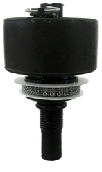
Tsunami water separators and oil coalescing filters are designed to accommodate multiple drain types for specific application needs. Draining options include float drains, our patented Moisture Minder® Electronic Drain and our patent pending pneumatic filter drain
FLOAT DRAIN
Standard with all filters
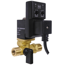
MOISTURE MINDER® EDV
A fixed strainer screen removes contaminates before reaching the valve orifice.
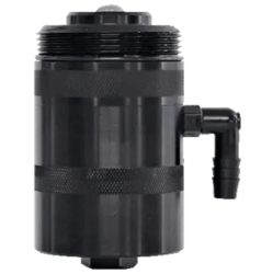
MOISTURE MINDER® FILTER DRAIN
Requires an intermittent pilot signal to operate. Designed to spin on corresponding size filter housing.
FILTRATION PACKAGES
PACKAGE 1
Includes:- Water Separator
- Lubricator
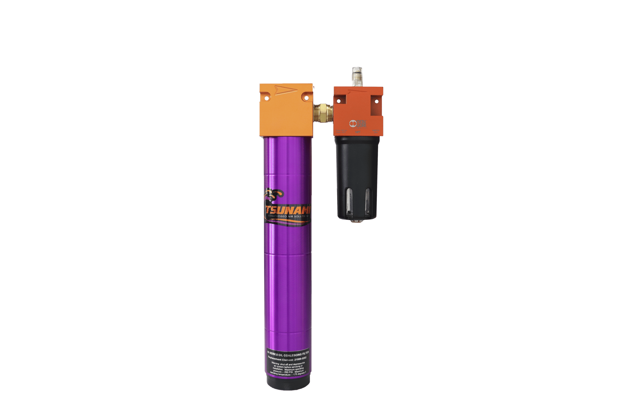
| ITEM # | MAX CFM | PORT SIZE | WEIGHT | DIMENSIONS (HWD) |
|---|---|---|---|---|
21999-0416 |
20 |
¼” NPT |
2½ lbs |
9½” x 4½” x 2½” |
21999-0247 |
50 |
½” NPT |
7 lbs |
18” x 6” x 5” |
21999-0248 |
120 |
1” NPT |
12 lbs |
19½” x 8” x 5½” |
PACKAGE 2
Includes:- Water Separator
- Regulator
- Lubricator
/21999-0249%2050%20CFM%20Filtration%20Package%202%20WEB.png?width=700&height=380&name=21999-0249%2050%20CFM%20Filtration%20Package%202%20WEB.png "21999-0249 50 CFM Filtration Package 2 WEB")
| ITEM # | MAX CFM | PORT SIZE | WEIGHT | DIMENSIONS (HWD) |
|---|---|---|---|---|
21999-0415 |
20 |
¼” NPT |
3 lbs |
10½” x 5½” x 3½” |
21999-0249 |
50 |
½” NPT |
10½ lbs |
18” x 13” x 6½” |
21999-0249-R |
50 |
½” NPT |
10½ lbs |
18” x 13” x 6½” |
21999-0250 |
120 |
1” NPT |
16 lbs |
21” x 13” x 6½” |
“-R” indicates right to left flow
PACKAGE 3
Includes:- Water Separator
- Oil Coalescing Filter
/tsunami%2050%20cfm%20air%20package%20card%20flip.jpg?width=400&height=250&name=tsunami%2050%20cfm%20air%20package%20card%20flip.jpg "tsunami 50 cfm air package card flip")
| ITEM # | MAX CFM | PORT SIZE | WEIGHT | DIMENSIONS (HWD) |
|---|---|---|---|---|
21999-0424 |
20 |
¼” NPT |
3 lbs |
9½” x 5” x 2½” |
21999-0251 |
50 |
½” NPT |
7 9½ lbs |
18” x 6½” x 5” |
21999-0252 |
120 |
1” NPT |
14 lbs |
19½” x 8” x 5½” |
PACKAGE 4
Includes:- Water Separator
- Oil Coalescing Filter
- Regulator
/21999-0253%2050%20CFM%20Filtrattion%20Package%204.png?width=160&height=224&name=21999-0253%2050%20CFM%20Filtrattion%20Package%204.png "21999-0253 50 CFM Filtrattion Package 4")
| ITEM # | MAX CFM | PORT SIZE | WEIGHT | DIMENSIONS (HWD) |
|---|---|---|---|---|
21999-0677 |
20 |
¼” NPT |
3½ lbs |
9½” x 6½” x 3½” |
21999-0253 |
50 |
½” NPT |
12 lbs |
17” x 13” x 4½” |
21999-0253-R |
50 |
½” NPT |
12 lbs |
17” x 13” x 4½” |
21999-0254 |
120 |
1” NPT |
18 lbs |
21” x 13” x 6½” |
“-R” indicates right to left flow
PACKAGE 5
Includes:- Water Separator
- Oil Coalescing Filter
- Activated Carbon Filter
| ITEM # | MAX CFM | PORT SIZE | WEIGHT | DIMENSIONS (HWD) |
|---|---|---|---|---|
21999-0421 |
20 |
¼” NPT |
4 lbs |
9½” x 8” x 2½” |
21999-0255 |
50 |
½” NPT |
13½ lbs |
17” x 13” x 3½” |
21999-0255-R |
50 |
½” NPT |
13 lbs |
17” x 13” x 3½” |
21999-0256 |
120 |
1” NPT |
21 lbs |
21” x 13” x 6½” |
PACKAGE 6
Includes:- Water Separator
- Oil Coalescing Filter
- Activated Carbon Filter
- Regulator
%20updated.png?width=2000&height=1333&name=21999-0257%20(2022)%20updated.png "21999-0257 (2022) updated")
| ITEM # | MAX CFM | PORT SIZE | WEIGHT | DIMENSIONS (HWD) |
|---|---|---|---|---|
21999-0678 |
20 |
¼” NPT |
5 lbs |
10½” x 9” x 3½” |
21999-0257 |
50 |
½” NPT |
15½ lbs |
18½” x 17” x 4½” |
21999-0257-R |
50 |
½” NPT |
15½ lbs |
18½” x 17” x 4½” |
21999-0258 |
120 |
1” NPT |
25 lbs |
18½” x 17” x 4½” |
EDV Models Available: 20 SCFM: 21999-0457 50 SCFM: 21999-0291
PACKAGE 7
Includes:- Oil Coalescing Filter
- Regulator
/21999-0679%2050%20CFM%20Water%20Separator%20Regulator%20Filtration%20Package%208%20NEW%20web.png?width=100&height=184&name=21999-0679%2050%20CFM%20Water%20Separator%20Regulator%20Filtration%20Package%208%20NEW%20web.png "21999-0679 50 CFM Water Separator Regulator Filtration Package 8 NEW web")
| ITEM # | MAX CFM | PORT SIZE | WEIGHT | DIMENSIONS (HWD) |
|---|---|---|---|---|
21999-0969 |
20 |
¼” NPT |
2 lbs |
10½” x 4” x 3½” |
21999-0494 |
50 |
½” NPT |
6 lbs |
18½” x 6½” x 6” |
21999-0967 |
120 |
1” NPT |
12 lbs |
21” x 8” x 5½” |
PACKAGE 8
Includes:- Water Separator
- Regulator
| ITEM # | MAX CFM | PORT SIZE | WEIGHT | DIMENSIONS (HWD) |
|---|---|---|---|---|
21999-0414 |
20 |
¼” NPT |
2½ lbs |
10½” x 4” x 3½” |
21999-0679 |
50 |
½” NPT |
8 lbs |
18” x 6½” x 6” |
21999-0968 |
120 |
1” NPT |
12 lbs |
21” x 8” x 5½” |
“-R” indicates right to left flow
BREATHING AIR SYSTEMS
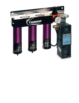
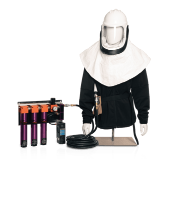
Tsunami Breathing Air Systems are the optimal solution when Grade D breathing air is required. The complete system features industry-leading Tsunami 3-stage filtration along with continuous carbon monoxide monitoring that can be used in any SAR (Supplied Air Respirator) system.
- 3-stage Tsunami filtration system with automatic float drains
- Easy-to-read digital carbon monoxide alarm
- CO monitor calibration made easy with Autocal®
- Meets OSHA Grade D breathing air quality specifications
BREATHING AIR
| ITEM # | DESCRIPTION | MAX CFM | PORT SIZE | DRAIN | MAX PSI | MAX °F | DIMENSIONS (HWD) |
|---|---|---|---|---|---|---|---|
21999-0265 |
Multi-User Breathing Air System - USA (10ppm) |
50 |
½ NPT |
Float |
250 |
175 |
16" x 18" x 5" |
21999-0980 |
Single-User Breathing Air System - USA (10ppm) |
20 |
¼ NPT |
Float |
250 |
175 |
13” x 12” x 5” |
21999-0265-CA |
Multi-User Breathing Air System - Canada (5ppm) |
50 |
½ NPT |
Float |
250 |
175 |
16" x 18" x 5" |
21999-0980 |
Single-User Breathing Air Panel - Canada (5ppm) |
20 |
¼ NPT |
Float |
250 |
175 |
13" x 12" x 5" |
Calibration videos available on our website

BREATHING AIR ACCESSORIES
GFG BREATHING AIR ACCESSORIES
| ITEM # | DESCRIPTION |
|---|---|
21999-0264 |
Calibration Kit for CO Monitor - GFG 7735-10 (This MUST drop ship from manufacturer to end user) |
21999-0263 |
CO Monitor for Tsunami Breathing Air Panel - GFG RAM 744 (10ppm) - USA |
21999-0263-CA |
CO Monitor for Tsunami Breathing Air Panel - GFG RAM (5ppm) - Canada |
21999-0267 |
110/120v Wall Pack Adaptor Replacement |
1450004 |
Replacement CO Sensor - RAM 744 |
AUTOMATIC DRAINS
Neglecting to consistently drain condensate and contamination will result in endless headaches and costly downtime. Inadequate or forgotten draining dramatically wears on filtration systems causing them to become ineffective and damaging to critical equipment and processes. Tsunami offers a variety of drain styles to assure timely and effective draining for your facility.
PNEUMATIC PISTON DRAINS
HOW IT WORKS
1. PILOT SIGNAL RECEIVED
Condensation enters left hand, or water inlet of valve.
MOISTURE MINDER® 1
/moisture%20minder%20explain%20image%201.jpg?width=400&height=250&name=moisture%20minder%20explain%20image%201.jpg)
MOISTURE MINDER® FILTER DRAIN
/pneumatic%20drain%20explain%20image%201.jpg?width=400&height=250&name=pneumatic%20drain%20explain%20image%201.jpg)
2. PILOT SIGNAL FROM UNLOADER
Piston shifts, closing off drain port. As piston moves, it will open up the stainless ball check allowing condensate to be forced into pressurized discharge reservoir.
/moisture%20minder%20explain%20image%202.jpg?width=400&height=250&name=moisture%20minder%20explain%20image%202.jpg)
/pneumatic%20drain%20explain%20image%202.jpg?width=400&height=250&name=pneumatic%20drain%20explain%20image%202.jpg)
3. VALVE AT REST
When pilot signal is relieved, piston returns to relaxed position. The ball check closes preventing zero pressure loss in the system. The drain port opens and the stored condensate is ejected.
/moisture%20minder%20explain%20image%203.jpg?width=400&height=250&name=moisture%20minder%20explain%20image%203.jpg)
/pneumatic%20drain%20explain%20image%203.jpg?width=400&height=250&name=pneumatic%20drain%20explain%20image%203.jpg)
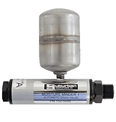
MOISTURE MINDER® PNEUMATIC DRAIN
Powered by a pneumatic pilot signal. Drain Minder Cotroller can be used to cycle pneumatic drains.
| ITEM # | MAX PSI | PORT SIZE | WEIGHT | DIS (HWD) |
|---|---|---|---|---|
152-0000 |
250 |
¼” NPT |
2 lbs |
5” x 5½” x 2” |
21999-0317 |
Pneumatic Drain Installation Kit |
Pneumatic Drain Installation Kit |
Pneumatic Drain Installation Kit |
Pneumatic Drain Installation Kit |
21999-0300 |
Universal Strainer w/ 50 mesh screen |
Universal Strainer w/ 50 mesh screen |
Universal Strainer w/ 50 mesh screen |
Universal Strainer w/ 50 mesh screen |
MOISTURE MINDER® FILTER DRAIN
Designed to spin on the corresponding size Tsunami filter tube.
/21999-0805%20120%20SCFM%20Moisture%20Minder%20Pneumatic%20Filter%20Drain%20w%20shadow.png?width=280&height=350&name=21999-0805%20120%20SCFM%20Moisture%20Minder%20Pneumatic%20Filter%20Drain%20w%20shadow.png "21999-0805 120 SCFM Moisture Minder Pneumatic Filter Drain w shadow")
| ITEM # | FILTER SIZE | MAX PSI | WEIGHT | DIS (HWD) |
|---|---|---|---|---|
21999-0792 |
20 CFM |
250 |
1 lbs |
4” x 3” x 2” |
21999-0795 |
50 CFM |
250 |
1 lbs |
4” x 3½” x 3½” |
21999-0805 |
120/240 CFM |
250 |
1½ lbs |
4” x 3½” x 3” |
ELECTRONIC DRAINS
MOISTURE MINDER® ELECTRONIC DRAIN VALVE (EDV)
The Moisture Minder® EDV incorporates a self-cleaning feature where a fixed strainer screen is used to capture contaminants before reaching the valve orifice. Opening the manual ball valve automatically flushes the strainer screen clean. The drain is compatible with various types of media and conforms to the NEMA 4 standard.
- Adjustable Timer: OFF: 0.5 - 45 minutes ON: 0.5 - 10 seconds
- Internal screen and ball valve allows for self cleaning
- Dual Size Inlet: Accommodates 1/4” I.D. or 1/2” OD NPT thread sizes
- 1/4 turn ball valve allows for self cleaning without disassembling
- IP65 Rating
HOW IT WORKS
1. TIMER ACTUATES
Condensation enters through the inlet side of valve. Debris is captured inside the internal strainer
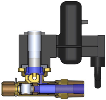
2. DEBRIS IS EJECTED
When valve activates condensate flows thru strainer up to the orifice and out the back discharge port. Debris is captured by internal strainer which prevents fouling.
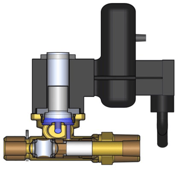
3. SELF CLEANING
Only open ¼” ball valve to clean strainer or to manually drain the tank.
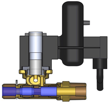
MOISTURE MINDER® ELECTRONIC DRAIN VALVE
| ITEM # | POWER | DUAL SIZE INLET | MAX PSI | WEIGHT | DIMENSIONS (HWD) |
|---|---|---|---|---|---|
21999-0177 |
115v AC / 60Hz |
¼” ID & ½” OD |
230 |
1 lb |
5½” x 3½” x 3½” |
21999-0177-230 |
115v AC / 60Hz220v AC / 60Hz |
¼” ID & ½” OD |
230 |
1 lb |
5½” x 3½” x 3½” |
21999-0177-24 |
24v DC |
¼” ID & ½” OD |
230 |
1 lb |
5½” x 3½” x 3½” |
21999-0177-12 |
12v DC |
¼” ID & ½” OD |
150 |
1 lb |
5½” x 3½” x 3½” |
21999-0316 |
21999-0316 Electronic Drain Installation Kit |
21999-0316 Electronic Drain Installation Kit |
21999-0316 Electronic Drain Installation Kit |
21999-0316 Electronic Drain Installation Kit |
21999-0316 Electronic Drain Installation Kit |
DRAIN MINDER II CONTROLLER
Provides the pilot signal every .5 to 45 minutes to multiple pneumatic drains.
/Drain%20Minder%20II.png?width=410&height=390&name=Drain%20Minder%20II.png "Drain Minder II")
| ITEM # | DESCRIPTION |
|---|---|
144-0001 |
Drain Minder II Controller - 110v |
144-0001-12 |
Drain Minder II Controller - 12v |
FLOAT DRAIN REPLACEMENT
Includes 3 float drains and o-rings for replacement in Tsunami filters.
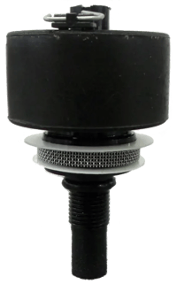
| ITEM # | DESCRIPTION |
|---|---|
21999-0868 |
21999-0868 Float Drain 3-Pack |
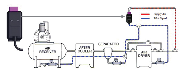
HOW IT WORKS DRAIN MINDER II AUTOMATIC TIMER
The Drain Minder II can deliver the pilot signal needed to operate the Moisture Minder pneumatic drain valves when no other intermittent pilot signal is available. The control is installed in the typical system by teeing into a filtered air supply and connecting the supply line to the inlet side of the controller solenoid.
COMPRESSED AIR ACCESSORIES
AIR MONITORING EQUIPMENT
Tsunami Air Monitoring Equipment provides the ability to verify that the air system tested is supplying the quality of compressed air cleanliness required for the application.
- Air Prep Kit
- Includes Air Survey Monitor and CFM Test Kit
- Air Survey Monitor
- Measures humidity, dew point, and air temperature
- Easy to read LCD screen
- Includes sensor filtration
- CFM Test Kit (3 - 30 CFM)
- Measure the CFM usage at any tool
- Easy to read graph
COMPRESSED AIR ACCESSORIES
| ITEM # | DESCRIPTION | WEIGHT | DIMENSIONS (LWH) |
|---|---|---|---|
21999-0938 |
Air Prep Kit (A) |
8.5 lbs |
13" x 17" x 4" |
21999-0440 |
Air Survey Kit (B) |
5.5 lbs |
13" x 17" x 4" |
21999-0447 |
CFM Test Kit (C) |
5 lbs |
13" x 17" x 4" |
ULTRA-FLO SPRAY HOSE
The extremely lightweight Tsunami Ultra-flo Spray Hose is designed to bring both longevity and performance to the toughest applications. Engineered for high-temperature exposure, this lay-flat hose features a proprietary internal coating which prevents breakdown caused by heat and harmful chemicals. The Ultra-Flo Spray Hose is also equipped with an anti-static strip to reduce or elminate static build-up.
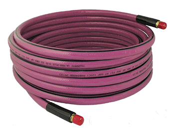
ULTRA-FLO SPRAY HOSE
| ITEM # | HOSE LENGTH | HOSE QUANTITY | NPT | HOSE I.D. | WEIGHT |
|---|---|---|---|---|---|
21999-0495 |
5' |
1 |
1/4" Male |
3/8" |
2 lbs |
21999-0449 |
35' |
1 |
1/4" Male |
3/8" |
4.5 lbs |
21999-0450 |
50' |
1 |
1/4" Male |
3/8" |
5.5 lbs |
21999-0783 |
35' |
10 pack |
1/4" Male |
3/8" |
4.5 lbs |
21999-0784 |
50' |
5 pack |
1/4" Male |
3/8" |
5.5 lbs |
HIGH-FLOW COUPLERS
10 PACK
Prevost Venting-Action couplers are designed to eliminate hose whip.
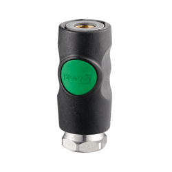
| ITEM # | DESCRIPTION |
|---|---|
| 21999-0831 | ¼” Female (sold in 10 pack) |
| 21999-0832 | ¼” Male (sold in 10 pack) |
HIGH-FLOW PLUGS
10 PACK
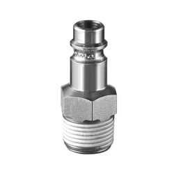
| ITEM # | DESCRIPTION |
|---|---|
| 21999-0833 | ¼” Female (sold in 10 pack) |
| 21999-0834 | ¼” Male (sold in 10 pack) |
BLOW GUN
10 PACK
Nylon Tip OSHA Compliant Blow Gun
/blow_gun_web%20bucket.png?width=250&height=263&name=blow_gun_web%20bucket.png)
| ITEM # | DESCRIPTION |
|---|---|
| 21999-0835 | ¼” Inlet (sold in 10 pack) |
COMPRESSED AIR ACCESSORIES FILTERS, REGULATORS, AND LUBRICATORS
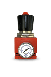
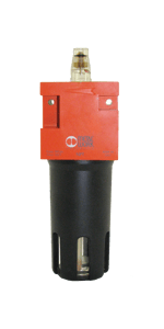
REGULATORS WITH GAUGE
232 max PSI, 122°F max temp
| ITEM # | MAX FLOW | PORT SIZE | WEIGHT | DIMENSIONS (HWD) |
|---|---|---|---|---|
21999-0870 |
25 SCFM |
¼” NPT |
1 lbs |
4" x 2" x 3" |
21999-0871 |
89 SCFM |
½” NPT |
2 lbs |
5” x 2½” x 3½” |
21999-0872 |
160 SCFM |
1” NPT |
3½ lbs |
7½” x 3” x 4½” |
LUBRICATORS
| ITEM # | MAX FLOW | PORT SIZE | RESEVOIR | WEIGHT | DIMENSIONS (HWD) |
|---|---|---|---|---|---|
21999-0298 |
25 CFM |
¼” NPT |
50 mL |
1 lb |
6½" x 2" x 2" |
21999-0195 |
153 CFM |
½” NPT |
150 mL |
2 lbs |
8” x 2½” x 2½” |
21999-0196 |
565 CFM |
1” NPT |
380 mL |
2½ lbs |
10” x 3” x 3” |
21999-0361 |
565 CFM |
1” NPT |
1088 mL |
5 lbs |
17” x 3½” x 3½” |
ACCESSORIES
| ITEM # | DESCRIPTION |
|---|---|
4338228 |
Pressure Gage - (0-200 PSI) - fits ⅛” back mount - ¼” NPT & ½” NPT Regulators |
21999-0946 |
Pressure Gage - (0-200 PSI) - fits ¼” back mount - 1” NPT Regulators |
8825701 |
Filter-Regulator-Lubricator - ¼” NPT - 25 SCFM (F/R/L) |
21999-0874 |
Regulator Rebuild Kit 50 Series - adjustment knob and replacement bottom end |
Multiple configurations available upon request
SERVICE
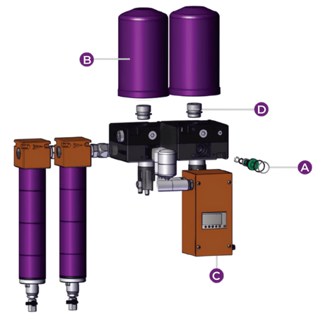
REGENERATIVE DRYER
| ITEM # | DESCRIPTION |
|---|---|
A 21999-0707 |
Piston Replacement Kit for Regenerative Dryer |
A 21999-1149 |
Dryer Piston O-Ring Service Kit - 12 Pistons |
B 21999-0976 |
Tower Replacement (Purple) - Pure-1, 3, 5 Dryers only |
B 21999-0976-BK |
Tower Replacement (Black) - Pure-1, 3, 5 Dryers only |
B 21999-0349 |
Tower Replacement (Purple) - Pure-7, 10, & Ultra Series |
B 21999-0349-BK |
Tower Replacement (Black) - Pure-7, 10, & Ultra Series |
C 21999-0672-10 |
PLC for 10HP Regenerative Dryer |
C 21999-0672 |
PLC for Regenerative Dryer (15HP or larger) |
C 21999-1139 |
PLC, Rail Dryer Controller, 4 MM Pneumatic Drains, 120VAC |
C 21999-1141 |
PLC, Rail Dryer Controller, 4 MM Pneumatic Drains, 24VDC |
C 21999-0672-BK |
PLC - Custom Dryer |
- 21999-0951 |
Pneumatic Timer Dryer Control - 2 outputs |
- 21999-0714 |
Power Supply - Regenerative Dryer |
- 21999-0714-G |
Global Power Supply - Regenerative Dryer |
- 21999-1133 |
PLC Direct Current (DC) Power Cord; 6’ 18 AWG Flying Leads, Barrel Connector |
- 21999-0941 |
Timer Valve Assembly for 110v Dryer |
- 21999-0797 |
Air Valve Replacement |
- 21999-0797-12 |
Air Valve Replacement - 12v |
- 21999-0504 |
12v DC Timer / Coil Assembly |
- 21999-1012-24 |
24v DC Timer / Coil Assembly |
- 610928-01 |
110v AC Timer / Coil Assembly |
- 610934-01 |
220/230v AC Timer / Coil Assembly |
| ITEM # | DESCRIPTION |
|---|---|
D 21999-0650-15 |
Tower Mounting Stud/Regen Valve (.015”) - Pure-7, 10, Ultra |
D 21999-0650-24 |
Tower Mounting Stud/Regen Valve (.024”) - Pure-7, 10, Ultra |
D 21999-0650-30 |
Tower Mounting Stud/Regen Valve (.030”) - Pure-7, 10, Ultra |
D 21999-0650-45 |
Tower Mounting Stud/Regen Valve (.045”) - Pure-7, 10, Ultra |
D 21999-0650-60 |
Tower Mounting Stud/Regen Valve (.060”) - Pure-7, 10, Ultra |
D 21999-0650-80 |
Tower Mounting Stud/Regen Valve (.080”) - Pure-7, 10, Ultra |
D 21999-0650-90 |
Tower Mounting Stud/Regen Valve (.090”) - Pure-7, 10, Ultra |
D 21999-1108-12 |
Tower Mounting Stud/Regen Valve (.012”) - Pure-1, 3, 5 |
D 21999-1108-15 |
Tower Mounting Stud/Regen Valve (.015”) - Pure-1, 3, 5 |
D 21999-1108-18 |
Tower Mounting Stud/Regen Valve (.018”) - Pure-1, 3, 5 |
D 21999-1108-30 |
Tower Mounting Stud/Regen Valve (.030”) - Pure-1, 3, 5 |
- 21999-1157 |
Muffler Replacement - Pure-1, 3, 5 Only |
- 21999-0700 |
Muffler Replacement - Pure-7, 10, & Ultra Series |
- 21999-1046 |
Muffler Core Replacement - Pure-10, & Ultra Series only |
- 21999-1165 |
Single Tower Dryer Heater 120 VAC - Pure-10 & Larger |
- 21999-1170 |
Single Tower Dryer Heater 12 VDC - Pure-10 & Larger (special order 8-12 week lead time required) |
- 21999-0937 |
Tsunami Dryer Heater 24 VDC - Pure-10 & Ultra Dryers |
- 21999-0712 |
Energy Saver Kit (Ultra dryer accessory only) |
- 21999-1038 |
Modular Dryer Subassembly Repl. - Ultra/Pure 10-20-30 |
- 21999-0529 |
Filter Assembly - Tsunami Ultra Regenerative Dryer |
- 21999-1135 |
Upgrade Kit; Pure-5 to Pure-5T |
INSTALLATION AND SERVICING

The Tsunami Learning Center hosts a wide range of informational blogs and videos including installation walk-throughs, step-by-step servicing, best practices, and more!
Visit tsunami.us.com to download catalogs and cut sheets, watch videos, and search for products.
Still have questions? Reach out to our sales team!
SERVICE PARTS
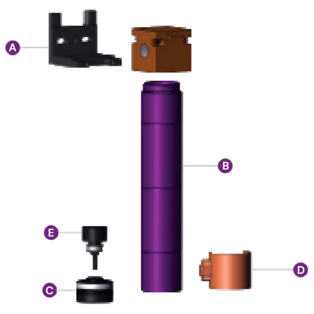
CORE DRYER
| ITEM # | DESCRIPTION |
|---|---|
- 21999-1230 |
Desiccant Cartridge Replacement |
- 21999-1146 |
Moisture Indicator - Replace Annually |
- 21999-1124 |
CORE Series Dryer End Cap |
- 21999-1077-PL |
Outer Tube Replacement |
- Q215-5716 |
Head Quad Ring Replacement |
BOTTOM CAP REPLACEMENT
| ITEM # | DESCRIPTION |
|---|---|
C 21999-0388 |
Bottom Cap - 20 Series |
C 21999-0127 |
Bottom Cap - 50 Series |
C 21999-0182 |
Bottom Cap - 120 / 240 Series |
C 21999-1148 |
Bottom Cap - 225 Series |
C 21999-1078 |
Bottom Cap - 300 Series |
C 21999-1158 |
Bottom Cap - 450 Series |
C 21999-1088 |
Bottom Cap - 600 Series |
C 21999-0961 |
Bottom Cap - 800 Series |
FILTRATION HARDWARE
| ITEM # | DESCRIPTION |
|---|---|
- 21999-0201 |
Drain Tube Kit - 10 Pack |
A 21999-0867 |
Mounting Bracket - 20 Series |
A 21999-0144 |
Mounting Bracket - 50 & 120 Series |
A 21999-1126 |
Mounting Bracket - 225/300/450/600 Series |
HEATER WRAPS
| ITEM # | DESCRIPTION |
|---|---|
D 163-0644 |
20 / 50 Series - 110 / 120v AC, 100W |
D 163-0648 |
20 / 50 Series - 12v DC, 75W |
D 163-0646 |
20 / 50 Series - 24 DC, 100W |
D 163-0649 |
120 / 240 Series - 110 / 120v AC, 150W |
D 163-0651 |
120 / 240 Series - 12v DC, 50W |
D 163-0650 |
120 / 240 Series - 24v DC, 120W |
D 163-0656 |
800 Series - 120v DC, 150W |
OUTER TUBE REPLACEMENT
| ITEM # | DESCRIPTION |
|---|---|
B 21999-0386 |
Outer Tube - 20 Series |
B 21999-0125 |
Outer Tube - 50 Series |
B 21999-0078 |
Outer Tube - 120 / 240 Series |
B 21999-1077-PL |
Outer Tube - 225/300 Series |
B 21999-1087-PL |
Outer Tube - 450/600 Series |
B 21999-0962-PL |
Outer Tube - 800 Series |
FILTER ACCESSORIES
| ITEM # | DESCRIPTION |
|---|---|
21999-0821 |
Condensation Collection Kit |
SERVICE PARTS
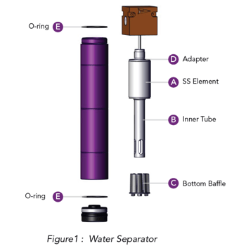
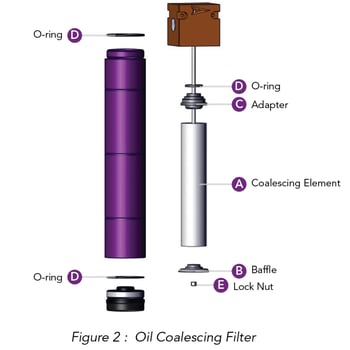
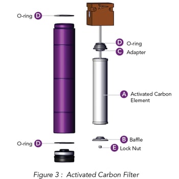
WATER SEPARATOR
| ITEM # | DESCRIPTION |
|---|---|
21999-0846 |
20 Series Water Separator Service Kit/ Pure-5 Regenerative Dryers - Includes A, B, C, D, E |
21999-0227 |
50 Series Water Separator Service Kit/ Pure-10 Regenerative Dryers - Includes A, B, C, D, E |
21999-0228 |
120 / 240 Series Water Separator Service Kit (240 requires x 2) Includes A, B, C, D, E |
21999-1098 |
225/300 Series Water Separator Service Kit - Includes A, B, C, D, E |
21999-1121 |
450/600 Series Water Separator Service Kit - Includes A, B, C, D, E |
21999-1005 |
800 Series Water Separator Service Kit - Includes A, B, C, D, E |
OIL COALESCING FILTER
| ITEM # | DESCRIPTION |
|---|---|
21999-0394 |
20 Series Oil Coalescing Filter Service Kit / Pure-5 Regenerative Dryers - Includes A, B, C, D, E |
21999-0202 |
50 / 120 / 240 / Pure-10 Series (240 requires x 2) - Includes A, B, C, D, E |
21999-0202-Z-SP |
Ultra Model Regenerative Dryer Oil Coalescing Service Kit |
21999-1099 |
225/300 Series Filter Service Kit - Includes A, B, C, D, E |
21999-1122 |
450/600 Series Filter Service Kit - Includes A, B, C, D, E |
21999-1069 |
800 Series Filter Service Kit - Includes A, B, C, D, E |
21999-0823 |
Pack of 5 (A) Elements - 20 Series Coalescing Element/ Pure-5 Series |
21999-0825 |
Pack of 5 (A) Elements - 50 / 120 / 240 / Pure-10 Series (240 requires x 2) |
21999-0828 |
Pack of 5 (A) Elements - Ultra Model Regenerative Dryer Coalescing Element |
ACTIVATED CARBON
| ITEM # | DESCRIPTION |
|---|---|
21999-0395 |
20 Series/ Pure-5 Regenerative Dryers - Includes A, B, C, D, E |
21999-0200 |
50 Series/ Pure-10 Regenerative Dryers - Includes A, B, C, D, E |
21999-1072 |
120 Series/ Ultra Regenerative Dryers - Includes A, B, C, D, E |
21999-0824 |
Pack of 5 (A) Elements - 20 Series/ Pure-5 Regenerative Dryers Activated Carbon Element |
21999-0826 |
Pack of 5 (A) Elements - 50 Series/ Pure-10 Regenerative Dryers Activated Carbon Element |
ANNUAL MANTENANCE KITS
| ITEM # | DESCRIPTION |
|---|---|
21999-0818 |
20 Series Annual Maintenance Kit - Includes (2) Biannual Coalescing and Activated Carbon Element Kits with O-rings |
21999-0819 |
50 Series Annual Maintenance Kit - Includes (2) Biannual Coalescing and Activated Carbon Element Kits with O-rings |
21999-1110 |
120 Series Annual Maintenance Kit - Includes (2) Biannual Coalescing and Activated Carbon Element Kits with O-rings |
DRYER STATS
AIR CONSUMPTION AVERAGES FOR TSUNAMI DRYERS*
| Unit | Max CFM | # of Towers | Orifice | CFM Consumption | Cycle Time for Tower Shifting | Total Time Tower is Drying | # of Towers Drying | # of Towers Regenerating |
|---|---|---|---|---|---|---|---|---|
21999-1134 |
5 |
2 |
.012 |
.3 |
2 min |
120 sec |
1 |
1 |
21999-1138 |
10 |
2 |
.015 |
.5 |
2 min |
120 sec |
1 |
1 |
21999-1105 |
15 |
2 |
.018 |
1 |
2 min |
120 sec |
1 |
1 |
21999-1140 |
25 |
2 |
.024 |
1.25 |
2 min |
120 sec |
1 |
1 |
21999-1010 |
40 |
2 |
.030 |
2.2 |
2 min |
120 sec |
1 |
1 |
21999-1020 |
80 |
4 |
.030 |
4.4 |
2 min |
120 sec |
2 |
2 |
21999-0710 |
40 |
2 |
.030 |
2.2 |
2 min |
120 sec |
1 |
1 |
21999-0715 |
60 |
3 |
.045 |
4 |
1 min |
120 sec |
2 |
1 |
21999-0720 |
80 |
4 |
.030 |
4.4 |
2 min |
120 sec |
2 |
2 |
21999-0730 |
120 |
4 |
.060 |
8 |
45 sec |
135 sec |
3 |
1 |
21999-0810 |
40 |
2 |
.030 |
2.2 |
2 min |
120 sec |
1 |
1 |
21999-0815 |
60 |
3 |
.045 |
4 |
1 min |
120 sec |
2 |
1 |
21999-0820 |
80 |
4 |
.030 |
4.4 |
2 min |
120 sec |
2 |
2 |
21999-0830 |
120 |
4 |
.060 |
8 |
45 sec |
135 sec |
3 |
1 |
21999-0740 |
160 |
8 |
.045 |
8 |
2 min |
120 sec |
4 |
4 |
21999-0750 |
200 |
8 |
.060 |
16 |
45 sec |
135 sec |
6 |
2 |
21999-0755 |
300 |
12 |
.060 |
24 |
45 sec |
135 sec |
9 |
3 |
21999-0760 |
400 |
16 |
.060 |
32 |
45 sec |
135 sec |
12 |
4 |
FLOW VOLUME THROUGH AN ORIFICE
The charts below indicate the volume of air consumed per orifice during the regeneration process; also known as "sweep air".
| Dryer Inlet Pressure |
Orifice Diameter | ||||||||
|---|---|---|---|---|---|---|---|---|---|
| 0.012" | 0.015" | 0.018" | 0.024" | 0.030" | 0.045" | 0.060" | 0.080" | .090" | |
| 100 PSI | 0.24 | 0.4 | 0.6 | 1.0 | 1.5 | 3.4 | 6.0 | 10.7 | 13.5 |
| 125 PSI | 0.29 | 0.5 | 0.7 | 1.2 | 1.9 | 4.1 | 7.3 | 13 | 16.4 |
| 150 PSI | 0.35 | 0.6 | 0.8 | 1.4 | 2.2 | 5 | 8.6 | 15.3 | 19.5 |
| 175 PSI | 0.40 | 0.7 | 0.9 | 1.6 | 2.5 | 5.6 | 10 | 17.6 | 22.3 |
FIND A DISTRIBUTOR

Looking for service parts or a complete system?
Find local and online retailers by visiting the Tsunami website and clicking “Buy Tsunami Products.”
Interested in becoming a Tsunami distributor? Reach out to our sales team!

.png?width=400&height=222&name=Suburban%20LOGO%20-%20Pantone-01%20(1).png)
Building value for our customers by producing quality, innovative, engineered, application-based products.
Suburban is an engineering driven organization that partners with our customers to design and develop unique and specific solutions for multiple application specific needs in the Defense, Hydraulics, Oil & Gas, Automotive, Agriculture, Construction, Utilities, and Industrial markets. In addition to custom engineered solutions, Suburban offers a complete line of standard products sold under the Python, LubeMinder®, and Tsunami brands.

CLEAN, DRY AIR
Providing the highest-grade clean, dry air, our systems filter out oil, water, and dirt that build up in compressed air systems and interrupt daily business
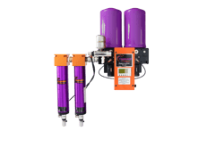
AIR DRYERS & FILTRATION
/21999-0980-Tsunami-Single-User-Breathing-Air-Package.png?width=250&height=238&name=21999-0980-Tsunami-Single-User-Breathing-Air-Package.png)
GRADE D BREATHING AIR
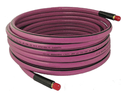
AIR HOSES, DRAINS & ACCESSORIES

MODERN DAY PROTECTION
Our lubrication systems automatically grease and oil machinery - reducing the overall time spent maintaining tools and increasing the life of equipment.
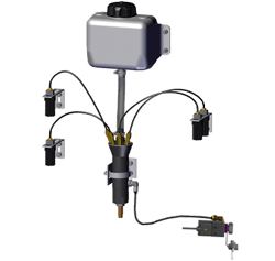
AUTOMATIC OILING SYSTEMS
.webp?width=520&height=402&name=Grease%20System%20Layout%20(4).webp)
AUTOMATIC GREASE SYSTEMS
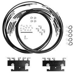
MANUAL GREASE BANK SYSTEMS
.png?width=250&height=105&name=Python%20Protective%20Sleeve%20and%20Covers%20PANTONE-01%20HORIZONTAL%20(1).png)
EQUIPMENT & OPERATOR PROTECTION
Protect hoses, wires, and cables from abrasion, temperature, moisture, and ruptures with our easy-to-use sleeves and straps.
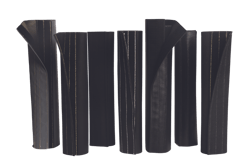
WRAP SLEEVES
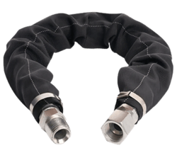
TUBULAR SLEEVES
/OEM%20Applications%20for%20Heavy-Duty%20Velcro%20Straps.png?width=250&height=141&name=OEM%20Applications%20for%20Heavy-Duty%20Velcro%20Straps.png)
BUNDLING STRAPS

© 2026 Suburban Manufacturing